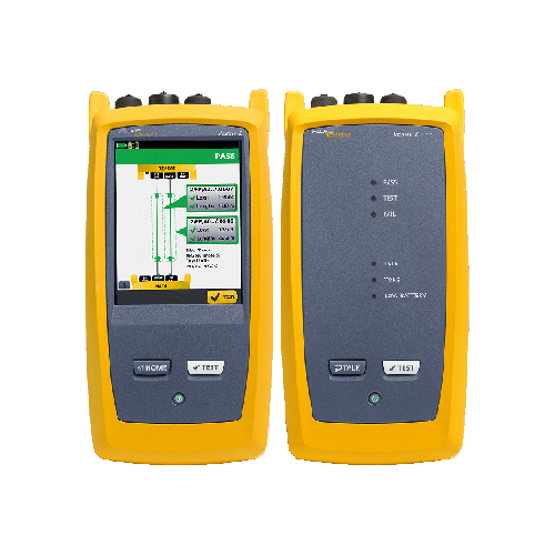
Fluke OptiFiber Pro OTDR Family
- Accurate and Reliable Measurements: Precise measurement of fiber loss, distance, and event location.
- Advanced Event Identification: Automatic identification and categorization of fiber events.
- User-Friendly Interface: Intuitive interface for easy operation.
- Flexible Configuration: Customizable test settings and reporting options.
- Efficient Workflow: Streamlined testing processes with automated features.
- Comprehensive Reporting: Detailed test reports for documentation and compliance.
- Description
- Additional information
- Specifications
Description
The Fluke OptiFiber Pro is a high-performance Optical Time Domain Reflectometer (OTDR) designed to ensure the integrity of fiber optic networks. This powerful tool offers a comprehensive solution for fiber optic testing, certification, and troubleshooting.
Key Features:
- Accurate and Reliable Measurements: Delivers precise measurements of fiber loss, distance, and event location, ensuring accurate network assessment.
- Advanced Event Identification: Automatically identifies and categorizes fiber events like connectors, splices, bends, and breaks, streamlining troubleshooting.
- User-Friendly Interface: The intuitive interface simplifies operation, making it accessible to technicians of all skill levels.
- Flexible Configuration: Customizable test settings and reporting options cater to diverse testing needs.
- Efficient Workflow: Streamlines testing processes with automated features and efficient data management.
- Comprehensive Reporting: Generates detailed test reports, facilitating documentation and compliance.
Benefits:
- Enhanced Network Performance: Identifies and resolves fiber issues promptly, ensuring optimal network performance.
- Reduced Downtime: Accelerates troubleshooting and repair processes, minimizing service disruptions.
- Improved Efficiency: Streamlines testing procedures, saving time and resources.
- Accurate Documentation: Provides detailed test reports for compliance and future reference.
By leveraging the Fluke OptiFiber Pro, network professionals can confidently assess and maintain fiber optic networks, ensuring reliable and high-performance connectivity. This powerful tool is essential for organizations seeking to build and maintain high-speed, reliable fiber optic networks.
Additional information
| Brand | Fluke Networks |
|---|
OptiFiber Pro Specifications
| Multimode Module (OFP2-100-M) |
Singlemode Module (OFP2-100-S) |
Quad Module (OFP2-100-Q) |
|
| Wavelengths | 850 nm +/- 10 nm 1300 nm +35/-15 nm |
1310 nm +/- 25 nm 1550 nm +/- 30 nm |
850 nm +/- 10 nm, 1300 nm +35/-15 nm, 1310 nm +/- 25 nm, 1550 nm +/- 30 nm |
| Compatible fiber types | 50/125 µm 62.5/125 µm |
Singlemode | 50/125 μm, 62.5/125 μm, Singlemode |
| Event dead zone 1 | 850 nm: 0.5 m (typical) 1300 nm: 0.7 m (typical) |
1310 nm: 0.6 m (typical) 1550 nm: 0.6 m (typical) |
850 nm: 0.5 m (typical), 1300 nm: 0.7 m (typical), 1310 nm: 0.6 m (typical), 1550 nm: 0.6 m (typical) |
| Attenuation dead zone 2 | 850 nm: 2.5 m (typical) 1300 nm: 4.5 m (typical) |
1310 nm: 3.6 m (typical) 1550 nm: 3.7 m (typical) |
850 nm: 2.5 m (typical), 1300 nm: 4.5 m (typical), 1310 nm: 3.6 m (typical), 1550 nm: 3.7 m (typical) |
| Dynamic range 3, 5, 6 | 850 nm: 28 dB (typical) 1300 nm: 30 dB (typical) |
1310 nm: 32 dB (typical) 1550 nm: 30 dB (typical) |
850 nm: 28 dB (typical), 1300 nm: 30 dB (typical), 1310 nm: 32 dB (typical), 1550 nm: 30 dB (typical) |
| Max distance range setting | 40 km | 130 km | MM: 40 km, SM: 130 km |
| Distance measurement range 4, 5, 7, 8, 9, 10 |
850 nm: 9 km 1300 nm: 35 km |
1310 nm: 80 km 1550 nm: 130 km |
850 nm: 9 km, 1300 nm: 35 km, 1310 nm: 80 km, 1550 nm: 130 km |
| Reflectance range 4, 5 | 850 nm: -14 dB to -57 dB (typical) 1300 nm: -14 dB to -62 dB (typical) |
1310 nm: -14 dB to -65 dB (typical) 1550 nm: -14 dB to -65 dB (typical) |
850 nm: -14 dB to -57 dB (typical), 1300 nm: -14 dB to -62 dB (typical), 1310 nm: -14 dB to -65 dB (typical), 1550 nm: -14 dB to -65 dB (typical) |
| Sample resolution | 3 cm to 400 cm | 3 cm to 400 cm | 3 cm to 400 cm |
| Pulse widths (nominal) | 850 nm: 3, 5, 20, 40, 200 ns 1300 nm: 3, 5, 20, 40, 200, 1000 ns |
3, 10, 30, 100, 300, 1000, 3000, 10000, 20000 ns |
850 nm: 3, 5, 20, 40, 200 ns, 1300 nm: 3, 5, 20, 40, 200, 1000 ns, 1310/1550 nm: 3, 10, 30, 100, 300, 1000, 3000, 10000, 20000 ns |
| Test time (per wavelength) | Auto setting: 5 sec (typical) | Auto setting: 10 sec (typical) | Auto setting: MM – 5 sec (typical) SM – 10 sec (typical) |
| Quick test setting: 2 sec (typical) | Quick test setting: 5 sec (typical) | Quick test setting: MM – 2 sec (typical) SM – 5 sec (typical) |
|
| Best resolution setting: 2 to 180 sec | Best resolution setting: 5 to 180 sec | Best resolution setting: MM – 2 to 180 sec SM – 5 to 180 sec |
|
| FaultMap setting: 2 sec (typical), 180 sec (max) |
FaultMap setting: 10 sec (typical), 180 sec (max) |
FaultMap setting: MM – 2 sec (typical) MM – 180 sec (max) SM – 10 sec (typical) SM – 180 sec (max) |
|
| DataCenter OTDR setting: 1 sec (typical at 850 nm), 7 sec (max) |
DataCenter OTDR setting: 20 sec (typical), 40 sec (max) |
DataCenter OTDR setting: MM – 1 sec (typical at 850 nm) MM – 7 sec (max) SM – 20 sec (typical) SM – 40 sec (max) |
|
| Manual setting: 3, 5, 10, 20, 40, 60, 90, 120, 180 sec |
Manual setting: 3, 5, 10, 20, 40, 60, 90, 120, 180 sec |
Manual setting: MM – 3, 5, 10, 20, 40, 60, 90, 120, 180 sec SM – 3, 5, 10, 20, 40, 60, 90, 120, 180 sec |
|
| 1. Measured at 1.5 dB below non-saturating reflection peak with the shortest pulse width. Reflection peak ‹ -40 dB for multimode and ‹ – 50 dB for singlemode. 2. Measured at +/- 0.5 dB deviation from backscatter with the shortest pulse width. Reflection peak ‹ -40 dB for multimode and ‹ – 50 dB for singlemode. 3. For typical backscatter coefficient for OM1 fiber: 850: -65 dB, 1300: -72 dB. 4. Typical backscatter and attenuation coefficients for OM2-OM4 fiber: 850 nm: -68 dB; 2.3 dB/km: 1300 nm: -76 dB; 0.6 dB/km. 5. Typical backscatter and attenuation coefficients for OS1-OS2 fiber: 1310nm : -79 dB; 0.32 dB/km; 1550 nm: -82 dB; 0.19 dB/km. 6. SNR=1 method, 3 minute averaging, widest pulse width. 7. 850 = 9 km typical to find the end or 7 km typical to find a 0.1 dB event (with a maximum of 18 dB attenuation prior to the event). 8. 1300 = 35 km typical to find the end or 30 km typical to find a 0.1 dB event (with a maximum of 18 dB attenuation prior to the event). 9. 1310 = 80 km typical to find the end or 60km typical to find a 0.1 dB event (with a maximum of 20 dB attenuation prior to the event). 10. 1550 = 130 km typical to find the end or 90 km typical to find a 0.1 dB event (with a maximum of 18 dB attenuation prior to the event). |
|||