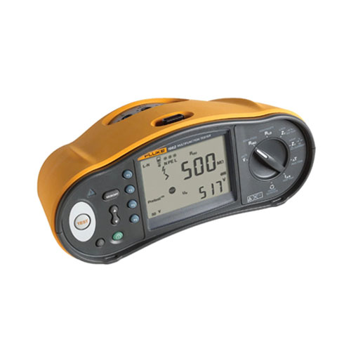

Fluke SMFT-1000 Solar Tools Kit: Fluke Multifunction PV Tester
- All-in-one PV system test solution: Covers both Category 1 and Category 2 tests according to IEC 62446-1 standards.
- I-V Curve Tracing: Analyzes the PV system’s performance and identifies potential issues.
- Open-circuit voltage (Voc) measurement: Measures the maximum voltage generated by a PV module or string.
- Short-circuit current (Isc) measurement: Measures the maximum current generated by a PV module or string.
- Insulation resistance (RINS) testing: Evaluates the insulation quality of PV modules and strings.
- Protective conductor resistance (RLO) measurement: Checks the integrity of the grounding system.
- Polarity testing: Verifies the correct polarity of PV modules and strings.
- Auto Test mode: Automates the testing sequence for various combinations of tests.
- Description
- Additional information
- Specifications
Description
The Fluke SMFT-1000 is a versatile tool designed to ensure the safety, efficiency, and reliability of photovoltaic (PV) systems. This multifunction PV tester and performance analyzer is a comprehensive solution for both installation and maintenance tasks.
Key Features:
- Full-Sequence Safety Testing: The SMFT-1000 performs essential safety tests like earth resistance, open-circuit voltage, short-circuit current, and insulation resistance, ensuring compliance with industry standards.
- I-V Curve Tracing: This feature allows for accurate measurement of the current-voltage characteristics of PV modules and strings, providing valuable insights into their performance.
- System Performance Testing: The tool can assess the overall performance of PV systems by measuring irradiance, temperature, tilt, and cardinal direction.
- Advanced Analysis: Powerful software analyzes test data and generates detailed reports, helping to optimize system performance and identify areas for improvement.
- Robust Design: Built to withstand harsh field conditions, the SMFT-1000 is durable and reliable.
- User-Friendly Interface: The intuitive interface simplifies testing procedures and data interpretation.
Applications:
- PV System Installation:
- Verifies correct installation of PV modules and inverters.
- Ensures compliance with safety standards and regulations.
- Identifies and troubleshoots installation issues.
- PV System Maintenance:
- Monitors system performance and identifies potential degradation.
- Detects and diagnoses faults in PV modules, inverters, and wiring.
- Optimizes system performance through regular testing and analysis.
- Quality Assurance:
- Assesses the quality of PV modules and systems.
- Verifies manufacturer’s specifications and performance claims.
- Ensures long-term reliability and efficiency.
By utilizing the Fluke SMFT-1000, technicians and engineers can efficiently troubleshoot, optimize, and maintain PV systems, maximizing their energy output and ensuring long-term performance.
Additional information
| Brand | Fluke |
|---|
Specifications: SMFT-1000 Solar Tools Kit: Fluke Multifunction PV Tester and Performance Analyzer, I-V Curve Tracer
| Fluke SMFT-1000 Multifunction PV Analyzer | |||
| Protective conductor resistance (RLo) | |||
| Display range | Measuring range | Resolution | Accuracy |
| 0.00 Ω – 19.99 Ω | 0.20 Ω – 19.99 Ω | 0.01 Ω | ± (2 % + 2 Digit) |
| 20.0 Ω- 199.9 Ω | 20.0 Ω – 199.9 Ω | 0.1 Ω | ± (2 % + 2 Digit) |
| 200 Ω – 2000 Ω | 200 Ω – 2000 Ω | 1 Ω | ± (5 % + 2 Digit) |
| Test current | ≥ 200 mA (≤ 2Ω + Rcomp) | ||
| Test voltage | 4 V DC … 10 V DC | ||
| Polarity reversing | Yes | ||
| Test lead zero (Rcomp) | Up to 3 Ω | ||
| PV module/PV string, open-circuit voltage (Voc) | |||
| Display range | Measuring range | Resolution | Accuracy |
| 0.0 V – 99.9 V | 5.0 V – 99.9 V | 0.1 V | ± (0.5 % + 2 Digit) |
| 100 V – 1000 V | 100 V – 1000 V | 1 V | ± (0.5 % + 2 Digit) |
| Polarity test | Yes | ||
| PV module/PV string, short-circuit current (Is/c) | |||
| Display range | Measuring range | Resolution | Accuracy |
| 0.0 A – 20.0 A | 0.2 A – 20.0 A | 0.1 A | ± (1 % + 2 Digit) |
| Insulation resistance (RINS) | |||
| Display range | Measuring range | Resolution | Accuracy |
| 0.00 MΩ – 99.99 MΩ | 0.20 MΩ – 99.99 MΩ | 0.01 MΩ | ± (5 % + 5 Digit) |
| 100.0 MΩ – 199.9 MΩ | 100.0 MΩ – 199.9 MΩ | 0.1 MΩ | ± (10 % + 5 Digit) |
| 200 MΩ – 999 MΩ | 200 MΩ – 999 MΩ | 1 MΩ | ± (20 % + 5 Digit) |
| Measuring range | Resolution | Accuracy | |
| Test voltage @ no load | 50 V / 100 V / 250 V up to 199.9 MΩ 500 V / 1000 V up to 999 MΩ |
1 V | 0 % to + 20 % |
| Test voltage @ ≥ 1 mA | 250 V @ 250 kΩ 500 V @ 500 kΩ 1000 V @ 1 MΩ |
1 V | 0 % to + 10 % |
| Testing current | Min. 1 mA (@ 250 kΩ / 500 kΩ / 1 MΩ) Max. 1.5 mA (short circuit) |
||
| Blocking diode checking (Vbd) | |||
| Display range | Measuring range | Resolution | Accuracy |
| 0.00 V DC – 6.00 V DC | 0.50 V DC – 6.00 V DC | 0.01 V DC | ± (5 % + 10 Digit) |
| Surge protection device (SPD) | |||
| Display range | Measuring range | Resolution | Accuracy |
| 0 V DC – 1000 V DC | 50 V DC – 1000 V DC | 1 V DC | ± (10 % + 5 Digit) |
| AC/DC voltage measurement via 4 mm test sockets | |||
| Display range | Measuring range | Resolution | Accuracy |
| 0.0 V AC – 99.9 V AC | 5.0 V AC – 99.9 V AC | 0.1 V | ± (2.5 % + 2 Digit) |
| 100 V AC – 700 V AC | 100 V AC – 700 V AC | 1 V | ± (2.5 % + 2 Digit) |
| 0.0 V DC – 99.9 V DC | 5.0 V DC – 99.9 V DC | 0.1 V | ± (2.5 % + 2 Digit) |
| 100 V DC – 1000 V DC | 100 V DC – 1000 V DC | 1 V | ± (2.5 % + 2 Digit) |
| Detection AC/DC | Yes (Automatic) | ||
| + / – polarity check | Yes | ||
| AC/DC current with i100 clamp | |||
| Display range | Measuring range | Resolution | Accuracy (DC, AC 50 Hz/60 Hz) |
| 0.0 A DC – 100 A DC | 1.0 A DC – 100 A DC | 0.1 A | ± (5 % + 2 Digit) * |
| 0.0 A AC – 100 A AC TRMS | 1.0 A AC – 100 A AC TRMS | 0.1 A | ± (5 % + 2 Digit) * |
| * i100 clamp tolerances not inclusive | |||
| i100 Clamp Tolerances | |||
| Display range | Measuring range | Output signal | Accuracy (DC, AC 50 Hz/60 Hz) |
| N/A | 1 A – 100 A DC or AC < 1 kHz | 10 mV/A AC/DC | ± (1.5 % + 0.1 A) |
| AC/DC Power measurement (with i100 clamp) | |||
| Display range | Measuring range | Resolution | Accuracy (DC, AC 50 Hz/60 Hz) |
| 0.0 V AC – 700 V AC 0.0 V DC – 1000 V DC |
5.0 V AC – 700 V AC 5.0 V DC – 1000 V DC |
0.1 V | ± (2.5 % + 2 Digit) |
| 0 A AC/DC – 100 A AC/DC | 1 A AC/DC- 100 A AC/DC | 0.1 A | ± (6.5 % + 3 Digit) |
| 0 kW/kVA – 100 kW/kVA | 5 kW/kVA – 100 kW/kVA | 1 kW/kVA | ± (10 % + 4 Digit) |
| General Specifications | |||
| SMFT-1000 size | 10 cm x 25.0 cm x 12.5 cm (3.8 in x 9.8 in x 4.9 in) | ||
| SMFT-1000 weight | 1.4 kg (3.09 lb) | ||
| Battery | 6 AA IEC LR6 | ||
| Operating temperature | 0 °C to 50 °C (32 °F to 122 °F) | ||
| Storage temperature | -30 °C to 60 °C (-22 °F to 140 °F) batteries removed | ||
| Operating altitude | up to 2000 m | ||
| Storage altitude | up to 2000 m | ||
| Safety | |||
| SMFT-1000 PV Analyzer | IEC 61010-1 Pollution Degree 2 IEC 61010-2-034 CAT III 1000 V dc, CAT III 700 V AC |
||
| i100 Current Clamp | IEC 61010-2-032, Type D (for insulated conductors), 1000 V | ||
| Accessories | IEC 61010-031 | ||
| TL1000-MC4 | CAT III 1500 V, 20 A | ||
| TP1000 Remote Probe (with cap) | CAT IV 600 V, CAT III 1000 V, 10 A | ||
| TP1000 Remote Probe (without cap) | CAT II 1000 V, 10 A | ||
| TL1000 Test Leads | CAT III 1000 V, 10 A | ||
| TL1000/30M Test Leads | CAT III 1000 V, CAT IV 600 V, 5 A (on reel) 10 A (fully extended) |
||
| TP74 Test Probes (with cap) | CAT III 1000 V, 10 A | ||
| TP74 Test Probes (without cap) | CAT II 1000 V, 10 A | ||
| AC285 Alligator Clip | CAT III 1000 V, 10 A | ||
| Performance | IEC 61557-1, IEC 61557-2, IEC 61557-4, IEC 61557-10 | ||
| Electromagnetic Compatibility (EMC) | |||
| International | IEC 61326-1: Portable Electromagnetic Environment, CISPR 11: Group 1, Class A Group 1: Equipment has intentionally generated and/or uses conductively-coupled radio frequency energy that is necessary for the internal function of the equipment itself. Class A: Equipment is suitable for use in all establishments other than domestic and those directly connected to a low-voltage power supply network that supplies buildings used for domestic purposes. There may be potential difficulties in ensuring electromagnetic compatibility in other environments due to conducted and radiated disturbances. Caution: This equipment is not intended for use in residential environments and may not provide adequate protection to radio reception in such environments. |
||
| Wireless Radio Module | |||
| Frequency Range | 2.402 GHz to 2.480 GHz | ||
| Output Power | 8 dBm | ||
Accurately measures modules with an efficiency of up to approximately 19%.