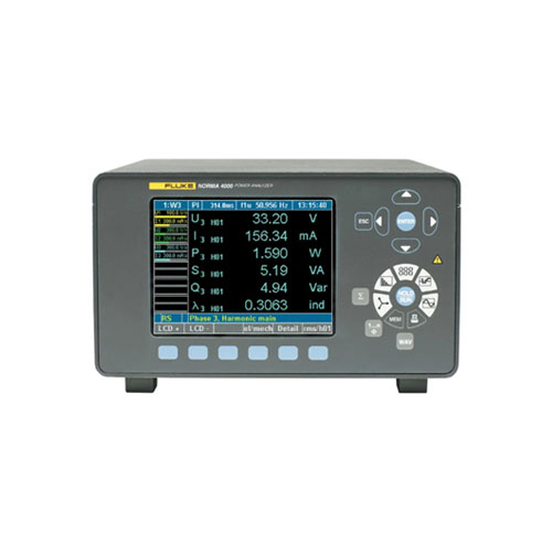
Fluke Norma 5000 Power Analyzers
- High-Precision Measurements: Accurately measures voltage, current, power, power factor, and energy consumption.
- Advanced Harmonic Analysis: Identifies and quantifies harmonic distortion up to the 40th harmonic.
- Fast Fourier Transform (FFT) Analysis: Provides a detailed frequency spectrum analysis.
- Transient Recording: Captures short-duration power quality disturbances for detailed analysis.
- Dynamic Measurements: Measures power quality parameters under varying load conditions.
- User-Friendly Interface: Intuitive interface for easy setup and operation.
- Flexible Configuration Options: Customizable to suit specific application needs.
- Robust and Durable Design: Built to withstand demanding environments.
- Powerful Analysis Software: In-depth analysis and reporting capabilities for comprehensive data interpretation.
- Description
- Specifications
- Models
Description
The Fluke Norma 5000 series is a family of high-precision power analyzers designed for the testing and development of power electronics. These compact and versatile instruments provide accurate and reliable measurements, making them essential tools for engineers and technicians in various industries.
Key Features:
- High-Precision Measurements: Accurately measures single-phase or three-phase voltage, current, power, power factor, and energy consumption.
- Advanced Harmonic Analysis: Identifies and quantifies harmonic distortion up to the 40th harmonic for detailed power quality analysis.
- Fast Fourier Transform (FFT) Analysis: Provides a comprehensive frequency spectrum analysis to identify and analyze frequency components.
- Transient Recording: Captures short-duration power quality disturbances to help diagnose intermittent problems.
- Dynamic Measurements: Measures power quality parameters under varying load conditions to assess system performance.
- User-Friendly Interface: Intuitive interface for easy setup and operation.
- Flexible Configuration Options: Customizable to suit specific application needs.
- Robust and Durable Design: Built to withstand demanding environments.
- Powerful Analysis Software: In-depth analysis and reporting capabilities for comprehensive data interpretation.
Applications:
- Motor and Drive Testing: Analyzing motor performance, efficiency, and power quality.
- Power Supply Testing: Assessing the performance of power supplies under different load conditions.
- Renewable Energy Systems: Monitoring the performance of solar, wind, and other renewable energy systems.
- Power Distribution Systems: Identifying and troubleshooting power quality problems in distribution systems.
- Research and Development: Developing and testing new power electronics devices and systems.
With its advanced features and user-friendly design, the Fluke Norma 5000 series empowers engineers and technicians to optimize the performance of power electronics systems, improve energy efficiency, and ensure reliable operation
Specifications: Fluke Norma 5000 Power Analyzers
| General Specifications | ||
| Number of Phases | 1 to 3 | |
| Weight | Approx. 5 kg (11 lb) | |
| Size | 150 x 237 x 315 mm | |
| 5.9 x 9.3 x 12.4 in | ||
| On-board Printer | No | |
| Display | Color, 5.7 in / 144 mm – 320 x 240 pixel | |
| User-selectable background lighting and contrast. | ||
| Bandwidth | DC to 3 MHz or DC to 10 MHz depending on input module | |
| Basic Accuracy | 0.2%, 0.1% or 0.03% depending on input modules | |
| Sampling Rate | 0.33 MHz or 1 MHz depending on input modules | |
| Voltage Input Range | 0.3 V to 1000 V | |
| Current Input Range (direct, not via shunt) | 0.03 mA to 20 A depending on input module | |
| Memory for Configurations | 4 MB | |
| Memory for Settings | 0.5 MB | |
| Fast Fourier Transformation (FFT) | To the 40th harmonic | |
| RS232/USB Interface | Standard | |
| PI1 Process interface (8 analog/impulse inputs and 4 analog outputs) | Optional | |
| IEEE 488.2/GPIB interface (1 MBit/s Ethernet / 10 MBit/s or 100 MBit/s) | Optional | |
| Fluke NormaView PC software (for data download, analysis and report writing) | Standard | |
| Basic Functions | ||
| Fast Fourier Transformation (FFT) | Calculation of harmonics with graphical representation. Up to 3 bar graphs are displayed at the same time. | |
| Measured values: U, I, P per phase | ||
| Order: 1st to 40th harmonics, maximum half sample frequency | ||
| Digital Oscilloscope (DSO) | Simultaneous display of up to 3 measured values on sample level. Quick view of curve form and distortion. | |
| Integration function (energy) | Simultaneous display of up to 6 configurable numeric values. Start/Stop conditions and positive negative direction available. | |
| Vector Display | Vector display of HO1 up to 6 signals. For easy testing of the right connection of the instrument and quick overview of the phase angle of each signal. | |
| Recorder | Display of average values over time for trend determination. | |
| RAM data memory | Storing of sample and average values; setting of start and stop conditions. | |
| From the RAM approximately 4 MB are available for the storage of measured values. | ||
| Configuration | Set up the analyzer to measure and display data in the format required. | |
| Ambient Conditions | ||
| Working Temperature Range | 5°C to 35°C (41°F to 95°F) | |
| Storage Temperature Range | -20°C to 50°C (-4°F to 122°F) | |
| Housing Material | Fluke Norma Power Analyzers are extremely compact and equipped with a solid metal case to meet stringent EMC requirements. | |
| Climatic Class | KYG DIN 40040, max. 85% relative humidity, non-condensing. | |
| Power supply | 85 V AC to 264 V AC, 50 Hz to 60 Hz, DC 100 to 260 V, ca. 40 VA European plug with switch. Binding post for current available on some models. | |
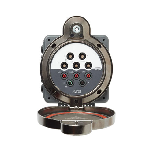
| Measuring Inputs | Safety sockets 4 mm, 2 for each input. External shunt connection over BNC socket. | |
| Operation | Membrane keyboard with cursor – function keys and direct functions. | |
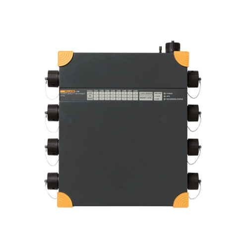
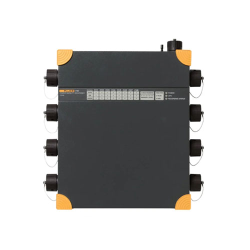
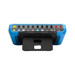
| Connections | Rear panel of the 3-phase Analyzer | |
| Measured Values | ||
Non-gapping calculation of averaged values for each phase. In three phase system additionally calculation of total power and averaging of V and I of the three phases. The fundamental H01 will be calculated in synchronous mode also for these values.
|
||
| Frequency and Synchronization | ||
| Range | DC and 0.2 Hz to sample rate | |
| Accuracy | ±0.01% of measured value (reading) | |
|
||
| Configuration Memory | ||
| Up to 15 user configurations can be saved into a permanent memory and reloaded later on. Changes that were not saved are lost after switching off the instrument. | ||
| Interface | ||
| RS232 interface for upload of firmware and data exchange with the PC. A printer can be connected over an external converter. | ||
| Options | IEEE 488.2 / 1 MBit/s | |
| Ethernet / 10 MBit/s or 100 Mbit/s | ||
| Standards and Safety | ||
| Electrical Safety | EN 61010-1 / 2nd Edition 1000 V CAT II (600V CAT III) | |
| Degree of pollution 2, safety Class I | ||
| EN 61558 for transformer | ||
| EN 61010-2-031/032 for accessories | ||
| Maximum inputs | For voltage inputs Measurement range 1000 Veff, 2 kVpeak | |
| For current inputs Measurement range 10 Aeff, 20 Apeak | ||
| Test voltage | Net input | case (protective conductor): 1.5 KV AC |
| Net connection | Measurement input: 5.4 kV AC | |
| Measurement inputs | Case: 3.3 kV AC | |
| Measurement input | input: 5.4 kV | |
| Electromagnetic susceptibility | Emission | IEC 61326-1, EN 50081-1, EN 55011 Class B |
| Immunity | IEC 61326-1 / Annex A (industrial sector), EN 50082-1 | |
Power Phases
The Fluke Norma 4000 Power Analyzer can be equipped with up to three power phases. Users can select the power phase best suited for their application.
Each modular plug-in power phase consists of a voltage and a current measurement channel. Each measuring channel is available for each basic unit, however only one kind of channel can be used per unit. Check standard configurations.
Power Phase Overview
| Power Phase Channels | ||
| PP42 | Accuracy | 0.2% (0.1% rd + 0.1% rg) |
| Current range | 20 A | |
| Sampling rate | 341 kHz | |
| Bandwidth | 3 MHz | |
| PP50 | Accuracy | 0.1% (0.05% rd + 0.05% rg) |
| Current range | 10 A | |
| Sampling rate | 1 MHz | |
| Bandwidth | 10 MHz | |
| PP54 | Accuracy | 0.1% (0.05% rd + 0.05% rg) |
| Current range | 10 A | |
| Sampling rate | 341 kHz | |
| Bandwidth | 3 MHz | |
| PP64 | Accuracy | 0.03% (0.02% rg + 0.01% rg) |
| Current range | 10 A | |
| Sampling rate | 341 kHz | |
| Bandwidth | 3 MHz | |
Current Shunts
| Planarshunt | |
| Continuous load (Imin) Range (Imax) |
0.3 A |
| 32 A | |
| Nominal current (calibration point) | 32 A |
| Basic accuracy at calibration point [%] | ± 0.03 |
| Basic accuracy at nominal current [%] | ± 0.03 |
| Nominal voltage drop [V] | 320 mV |
| Nominal resistance [Ohm] | 10 mΩ |
| Short time overrange (5s load 15s interval) |
100A/ 1s-5s |
| Overload Wmax | – |
| Bandwidth | DC – 1 MHz |
| Frequency range | – |
| Angular accuracy [°/kHz] | ± 0.1 |
| Frequency influence [%/kHz] | – |
| Load influence [%/A2] | – |
| Temperature coefficient [ppm/K] | ≤10 |
| Weight (kg / lbs) | 0.62 /1.36 |
| Triaxialshunts | |||
| Continuous load (Imin) Range (Imax) |
0.1 A | 1 A | 6 A |
| 30 A | 100 A | 300 A | |
| Nominal current (calibration point | 10 A | 30 A | 100 A |
| Basic accuracy at calibration point [%] | ± 0.03 | ± 0.03 | ± 0.1 |
| Basic accuracy at nominal current [%] | ± 0.03 | ± 0.03 | ± 0.1 |
| Nominal voltage drop [V] | 100 mV | 30 mV | 20 mV |
| Nominal resistance [Ohm] | 10 mΩ | 1 mΩ | 0.2 mΩ |
| Short time overrange (5s load 15s interval) | 35 A | 200 A | 450 A |
| Overload Wmax | 90 W | 200 W | 2 kW |
| Bandwidth | 2 MHz | 2 MHz | 1 MHz |
| Frequency range | 0 to 500 kHz | 0 to 200 kHz | 0 to 100 kHz |
| Angular accuracy [°/kHz] | ± 0.001 | ± 0.002 | ± 0.002 |
| Frequency influence [%/kHz] | ± 0.0015 | ± 0.0015 | ± 0.01 |
| Load influence [%/A2] | 1 x 10⁻⁶ | 1 x 10⁻⁶ | 1 x 10⁻⁶ |
| Temperature coefficient [ppm/K] | ≤15 | ≤15 | ≤10 |
| Weight (kg / lbs) | 0.75 / 1.65 | 0.75 / 1.65 | 1.2 / 2.65 |
| Triaxialshunts (Cont.) | |||
| Continuous load (Imin) Range (Imax) |
2 A | 18 A | 18 A |
| 450 A | 1000 A | 1500 A | |
| Nominal current (calibration point | 150 A | 300 A | 500 A |
| Basic accuracy at calibration point [%] | ± 0.1 | ± 0.1 | ± 0.1 |
| Basic accuracy at nominal current [%] | ± 0.1 | ± 0.1 | ± 0.1 |
| Nominal voltage drop [V] | 75 mV | 15 mV | 30 mV |
| Nominal resistance [Ohm] | 0.5 mΩ | 0.06 mΩ | 0.06 mΩ |
| Short time overrange (5s load 15s interval) | 650 A | 1500 A | 2000 A |
| Overload Wmax | 10 kW | 7.5 kW | 10 kW |
| Bandwidth | DC – 500 MHz | DC – 500 kHz | DC – 200 kHz |
| Frequency range | 0 to 100 kHz | 0 to 20 kHz | 0 to 20 kHz |
| Angular accuracy [°/kHz] | ± 0.025 | ± 0.025 | ± 0.025 |
| Frequency influence [%/kHz] | ± 0.03 | ± 0.03 | ± 0.03 |
| Load influence [%/A2] | 0.5 x 10⁻⁶ | 0.2 x 10⁻⁶ | 0.5 x 10⁻⁶ |
| Temperature coefficient [ppm/K] | ≤10 | ≤10 | ≤10 |
| Weight (kg / lbs) | 6 / 13.2 | 5.3 / 11.7 | 6 / 13.2 |
Models: Fluke Norma 5000 Power Analyzers
Includes:
- Power supply cable
- 5.7 in / 144 mm color display
- Internal printer
- RS232/USB interface for data download
- Space for six power-phases and options
- Fluke NormaView PC software
- User’s manual
- Test certificate
- Calibration values