
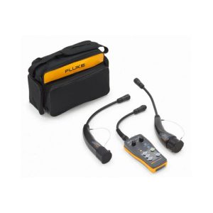
Fluke FEV300 EV Charging Station Test Adapter Kit
- Simulate current capabilities of charging cables
- Simulate various vehicle charging states
- Simulate earth fault
- Description
- Additional information
- Specifications
Description
The Fluke FEV300 is a versatile test adapter kit designed to ensure the safety and reliability of AC electric vehicle (EV) charging stations. This tool allows technicians to perform comprehensive tests on charging stations operating in mode 3, without the need for an actual EV.
Key Features:
- EV Simulation: The FEV300 mimics an electric vehicle, triggering the charging station’s functions and allowing for thorough testing.
- Safety Testing: It enables testing of crucial safety parameters like earth leakage and insulation resistance, ensuring compliance with safety standards.
- Functional Testing: The adapter facilitates functional tests, including the activation of charging cycles and the verification of voltage and current output.
- Wide Compatibility: The FEV300 supports various EV connector types, making it suitable for a broad range of charging stations.
- Robust Design: Built to withstand harsh working conditions, the IP54-rated FEV300 is durable and reliable.
How it Works:
Technicians can use the FEV300 in conjunction with other Fluke instruments like installation testers, multimeters, and oscilloscopes to perform a comprehensive range of tests. This ensures that EV charging stations are safe, efficient, and ready to provide reliable charging services.
Benefits of Using the Fluke FEV300:
- Increased Efficiency: The FEV300 streamlines the testing process, saving time and effort.
- Enhanced Safety: By identifying and addressing potential safety issues, the FEV300 helps to prevent accidents and ensure the safety of users.
- Improved Reliability: Regular testing with the FEV300 helps to maintain the optimal performance of EV charging stations.
- Compliance with Standards: The FEV300 helps to ensure that charging stations meet the necessary safety and performance standards.
By using the Fluke FEV300, technicians can play a crucial role in ensuring the safety and reliability of the growing EV charging infrastructure.
Additional information
| Brand | Fluke |
|---|
Specifications: Fluke FEV300 EV Charging Station Test Adapter Kit: Type 1 & 2 Connectors
| General features | |
| Input voltage | Up to 250 V (single phase system) / up to 480 V (three phase system), 50/60 Hz, max 10 A |
| Internal power consumption | 3 W max. |
| FEV300-CON-TY2 Plug | AC charging mode 3, suitable to IEC 62196-2 type 2 socket outlet or fixed cable with vehicle connector (type 2, 7P three-phase) |
| FEV300-CON-TY1 Plug | AC charging mode 3, suitable to IEC 62196-2 type 1 or SAE J1772 with vehicle connector (type 1, 5P single-phase) |
| Dimensions (H × W × D) | 110 × 45 × 220 mm length without connection cable and test cable |
| Weight (including type 1 or type 2 connection cable) | Approx. 1 kg |
| Safety standards | IEC/EN 61010-1, pollution degree 2 IEC/EN 61010-2-030, CAT II 300 V, protection class II |
| Ingress protection | IEC 60529: IP54 (housing) IEC 60529: IP54 (sockets with protection caps in place, connectors in connected condition or with protection caps in place, otherwise IP20) |
| Operating temperature | -20 °C to 40 °C |
| Storage temperature | -20 °C to 50 °C |
| Operating humidity range | 10 % to 85 % relative humidity non-condensing |
| Storage relative humidity | 0 % to 85 % non-condensing |
| Operating altitude | 2000 m max. |
| Functions | |
| PE Pre-Test | Visible indication >50 V AC/DC between PE conductor and touch sensor |
| PP Simulation | Open, 13 A, 20 A, 32 A, 63 A |
| CP States | State A, B, C, D |
| CP Error state “E” | On/off (CP signal short-circuited to PE) |
| PE Error state “F” (Earth fault) | On/off (interruption of PE conductor) |
| Outputs (for test purpose only) | |
| Measuring terminals L1, L2, L3, N, PE | Max. 250/480 V, max. 10 A |
| CP signal output terminals | Approx. +/-12 V |
| Caution: In case of wrong wiring or error of the charging station these terminals may be hazardous. | |
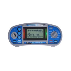
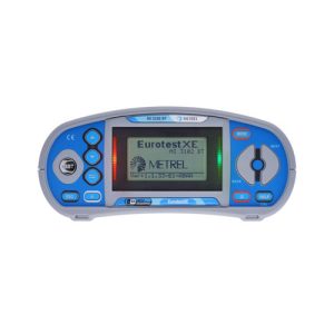
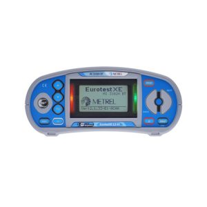
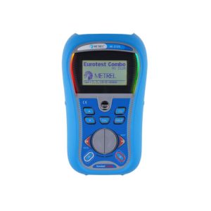
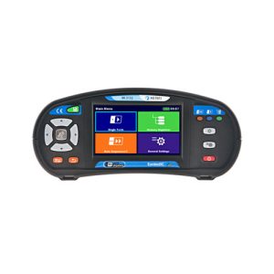
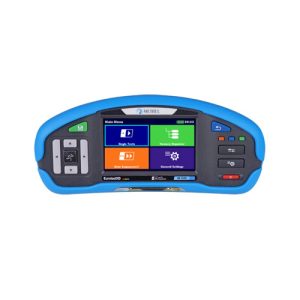
Related Products
- Tests voltage and frequency
- Checks wiring polarity to detect broken N wires
- Measures insulation resistance and loop and line resistance

- Tests continuity at L-N, N-PE inputs
- Tests smooth dc sensitive RCDs (Type B)
- Tests earth resistance, voltage, and frequency
- Offers multiple test voltages: 50 V, 100 V, 250 V, 500 V, 1000 V

- PE conductor can be tested for possible presence of dangerous voltage against earth
- Perform Cable Simulation with the PP State rotary switch simulating current capabilities of charging cables

- All-in-one PV system test solution meeting IEC 62446-1 standards for Category 1 and Category 2 tests
- Open-circuit voltage (VOC) measurement at the PV module/string up to 1000 V DC
- Insulation resistance with DC voltage from 50 V to 1000 V;
- Continuity of PE conductors with 200 mA test current with polarity change;
- Continuity of PE conductors with 7 mA test current without RCD tripping
- Insulation resistance with DC voltage from 50 V to 1000 V
- Continuity of PE conductors with 200 mA DC test current with polarity change
- Continuity of PE conductors with 7 mA test current without RCD tripping
- Insulation resistance with DC voltage 50 V to 2,5 kV and PI, DAR calculation
- Continuity of PE conductors with 200 mA DC test current with polarity change
- Continuity of PE conductors with 7 mA test current without RCD tripping

- Insulation resistance with DC voltage
- Continuity of PE conductors with 200 mA test current with polarity change
- Continuity of PE conductors with 7 mA test current (continuous measurement) without RCD tripping
- Insulation resistance with DC voltage
- Continuity of PE conductors with 200 mA test current with polarity change
- TRMS voltage and frequency
- Insulation resistance with DC voltage from 50 V to 1000 V
- Continuity of PE conductors with 200 mA DC test current with polarity change
- Continuity of PE conductors with 7 mA test current without RCD tripping

- Insulation resistance with DC voltage from 50 V to 2500 V and PI, DAR calculation
- Continuity of PE conductors with 200 mA DC test current with polarity change
- Continuity of PE conductors with 7 mA test current without RCD tripping
- Insulation resistance with DC voltage from 50 V to 2500 V and PI, DAR calculation
- Continuity of PE conductors with 200 mA DC test current with polarity change
- Continuity of PE conductors with 7 mA test current without RCD tripping