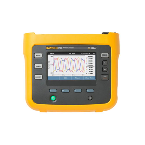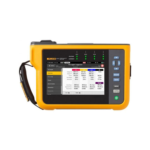
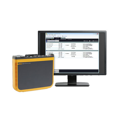
Fluke 1732 and 1734 Three-Phase Electrical Energy Loggers
- Automatic Data Logging: Continuously records critical power quality parameters.
- Easy-to-Use Interface: Intuitive design for simple setup and operation.
- Power Supply Flexibility: Can be powered directly from the measurement circuit.
- Robust Design: Built to withstand harsh environments.
- Accurate Measurements: Provides precise measurements of voltage, current, power, power factor, harmonics, and more.
- Data Analysis and Reporting: Allows for detailed analysis and reporting of power quality data.
- Remote Monitoring (1734): Wi-Fi connectivity enables remote monitoring and data access via the Fluke Connect app.
- Description
- Additional information
- Specifications
Description
The Fluke 1732 and 1734 are powerful and user-friendly power quality loggers designed to help you gain valuable insights into your electrical system’s performance. These devices automatically capture and record critical power quality parameters, making it easy to identify and address potential issues.
Key Features:
- Automated Data Capture: Continuously monitors and records key power quality parameters, including voltage, current, power, power factor, harmonics, and more.
- Intuitive User Interface: The simple and intuitive interface makes setup and operation effortless.
- Flexible Power Options: Can be powered directly from the measurement circuit, eliminating the need for external power sources.
- Robust Design: Built to withstand demanding environments and provide reliable performance.
- Comprehensive Data Analysis: Analyze recorded data to identify trends, anomalies, and potential issues.
- Remote Monitoring (1734): Wireless connectivity allows for remote monitoring and data access via the Fluke Connect app.
By utilizing the Fluke 1732 or 1734, you can:
- Improve Equipment Reliability: Identify and address power quality issues that can lead to equipment failures.
- Optimize Energy Efficiency: Analyze energy consumption patterns and identify opportunities for savings.
- Enhance System Performance: Monitor power quality to ensure optimal system performance.
- Comply with Standards: Verify compliance with electrical standards and regulations.
With their robust design, user-friendly interface, and advanced features, the Fluke 1732 and 1734 are essential tools for electrical professionals seeking to maintain and improve the reliability and efficiency of their electrical systems
Additional information
| Brand | Fluke |
|---|
Specifications: Fluke 1732 and 1734 Three-Phase Electrical Energy Loggers
| Specifications | |||||
| Accuracy | |||||
| Parameter | Range | Resolution | Intrinsic Accuracy at Reference Conditions (% of Reading +% of Full Scale) | ||
| Voltage | 1000 V | 0.1 V | ±(0.2% + 0.01%) | ||
| Current: Direct input | i17xx-flex 1500 12″ | 150 A | 0.1 A | ±(1% + 0.02%) | |
| 1500 A | 1 A | ±(1% + 0.02%) | |||
| i17xx-flex 3000 24″ | 300 A | 1 A | ±(1% + 0.03%) | ||
| 3000 A | 10 A | ±(1% + 0.03%) | |||
| i17xx-flex 6000 36″ | 600 A | 1 A | ±(1.5% + 0.03%) | ||
| 6000 A | 10 A | ±(1.5% + 0.03%) | |||
| i40s-EL clamp | 4 A | 1 mA | ±(0.7% + 0.02%) | ||
| 40 A | 10 mA | ±(0.7% + 0.02%) | |||
| Frequency | 42.5 Hz to 69 Hz | 0.01 Hz | ±(0.1%) | ||
| Auxillary input | ±10 V dc | 0.1 mV | ±(0.2% + 0.02%) | ||
| Voltage min/max | 1000 V | 0.1 V | ±(1% + 0.1%) | ||
| Current min/max | Defined by accessory | Defined by accessory | ±(5% + 0.2%) | ||
| THD on voltage | 1000% | 0.1% | ±0.5 | ||
| THD on current | 1000% | 0.1% | ±0.5 | ||
| Intrinsic Uncertainty ±(% of reading +% of range)¹ | |||||
| Parameter | Influence quantity | iFlex1500-12 | iFlex3000-24 | iFlex6000-36 | i40S-EL |
| 150 A / 1500 A | 300 A / 3000 A | 600 A / 6000 A | 4 A / 40 A | ||
| Active Power P | PF ≥ 0.99 | 1.2% + 0.005% | 1.2% + 0.0075% | 1.7% + 0.0075% | 1.2% + 0.005% |
| Active Energy Ea | PF ≥ 0.99 | 1.2% + 0.005% | 1.2% + 0.0075% | 1.7% + 0.0075% | 1.2% + 0.005% |
| Apparent power S | 0 ≤ PF ≤ 1 | 1.2% + 0.005% | 1.2% + 0.0075% | 1.7% + 0.0075% | 1.2% + 0.005% |
| Apparent Energy Eap | 0 ≤ PF ≤ 1 | 1.2% + 0.005% | 1.2% + 0.0075% | 1.7% + 0.0075% | 1.2% + 0.005% |
| Reactive power Q | 0 ≤ PF ≤ 1 | 2.5% of measured apparent power | |||
| Reactive Energy Er | 0 ≤ PF ≤ 1 | 2.5% of measured apparent power | |||
| Power Factor PF | – | ±0.025 | |||
| Displacement Power Factor | – | ±0.025 | |||
| DBF/cosϕ | – | ±0.025 | |||
| Additional uncertainty in% of range¹ | VP-N>250 V | 0.015% | 0.0225% | 0.0225% | 0.015% |
| ¹Range = 1000 V x Irange Reference conditions:
|
|||||
| Electrical Specifications | |
| Power Supply | |
| Voltage range | 100 V to 500 V using safety plug input when powering from the measurement circuit |
| 100 V to 240 V using standard power cord (IEC 60320 C7) | |
| Power consumption | Maximum 50 VA (max. 15 VA when powered using IEC 60320 input) |
| Efficiency | ≥ 68.2% (in accordance with energy efficiency regulations) |
| Maximum no-load consumption | < 0.3 W only when powered using IEC 60320 input |
| Mains power frequency | 50/60 Hz ±15% |
| Battery | Li-ion 3.7 V, 9.25 Wh, customer-replaceable |
| On-battery runtime | Four hours in standard operating mode, up to 5.5 hours in power saving mode |
| Charging time | < 6 hours |
| Data Acquisition | |
| Resolution | 16-bit synchronous sampling |
| Sampling frequency | 10.24 kHz at 50/60 Hz, synchronized to mains frequency |
| Input signal frequency | 50/60 Hz (42.5 to 69 Hz) |
| Circuit types | 1-φ, 1-φ IT, Split phase, 3-φ delta, 3-φ wye, 3-φ wye IT, 3-φ wye balanced, 3-φ Aron/Blondel (2-element delta), 3-φ delta open leg, Currents only (load studies) |
| Data storage | Internal flash memory (not user replaceable) |
| Memory size | Typical 10 logging sessions of 8 weeks with 1-minute intervals and 500 events¹ |
| ¹The number of possible logging sessions and logging period depends on user requirements. | |
| Basic Interval | |
| Measured parameters | Voltage, current, aux, frequency, THD V, THD A, power, power factor, fundamental power, DPF, energy |
| Averaging interval | User selectable: 1 sec, 5 sec, 10 sec, 30 sec, 1 min, 5 min, 10 min, 15 min, 30 min |
| Averaging time min/max values | Voltage, Current: Full cycle RMS updated every half cycle Aux, Power: 200ms |
| Demand Interval (Energy Meter Mode) | |
| Measured parameters | Energy (Wh, varh, VAh), PF, maximum demand, cost of energy |
| Interval | User selectable: 5 min, 10 min, 15 min, 20 min, 30 min, off |
| Standards Compliance | |
| Power | IEEE 1459 |
| Interfaces | |
| USB-A | File transfer via USB flash drive, firmware updates Max. current: 120 mA |
| WiFi | File transfer and remote control via direct connection or WiFi infrastructure |
| Bluetooth | Read auxiliary measurement data from Fluke Connect® 3000 series modules (requires 1734, or 1732 upgrade option) |
| USB-mini | Data download device to PC |
| Voltage Inputs | |
| Number of inputs | 4 (3 phases and neutral) |
| Maximum input voltage | 1000 Vrms, CF 1.7 |
| Input impedance | 10 MΩ |
| Bandwidth (-3 dB) | 42.5 Hz – 3.5 kHz |
| Scaling | 1:1 and variable |
| Measurement category | 1000 V CAT III/600 V CAT IV |
| Current Inputs | |
| Number of inputs | 3, mode selected automatically for attached sensor |
| Input voltage | Clamp input: 500 mVrms/50 mVrms; CF 2.8 |
| Rogowski coil input | 150 mVrms/15 mVrms at 50 Hz, 180 mVrms/18 mVrms at 60 Hz; CF 4; all at nominal probe range |
| Range | 1 A to 150 A/10 A to 1500 A with thin flexible current probe i17XX-flex1500 12″ |
| 3 A to 300 A/30 A to 3000 A with thin flexible current probe i17XX-flex3000 24″ | |
| 6 A to 600 A/60 A to 6000 A with thin flexible current probe i17XX-flex6000 36″ | |
| 40 mA to 4 A/0.4 A to 40 A with 40 A clamp i40s-EL | |
| Bandwidth (-3 dB) | 42.5 Hz – 3.5 kHz |
| Scaling | 1:1 and variable |
| Auxiliary Inputs | |
| Number of inputs | 2 |
| Input range | 0 to ±10 V dc, 1reading/s |
| Scale factor (available 2014) | Format: mx + b (gain and offset) user configurable |
| Displayed units (available 2014) | User configurable (7 characters, for example, °C, psi, or m/s) |
| Wireless Connection | |
| Number of inputs | 2 |
| Supported modules | Fluke Connect® 3000 series |
| Acquisition | 1 reading/s |
| Environmental Specifications | |
| Operating temperature | -10 °C to +50 °C (14 °F to 122 °F) |
| Storage temperature | -20 °C to +60 °C (-4 °F to 140 °F), with battery: -20 °C to +50 °C (-4 °F to 122 °F) |
| Operating humidity | 10 °C to 30 °C (50 °F to 86 °F) max. 95% RH |
| 30 °C to 40 °C (86 °F to 104 °F) max. 75% RH | |
| 40 °C to 50 °C (104 °F to 122 °F) max. 45% RH | |
| Operating altitude | 2000 m (up to 4000 m derate to 1000 V CAT II/600 V CAT III/300 V CAT IV) |
| Storage altitude | 12,000m |
| Enclosure | IP50 in accordance with EN60529 |
| Vibration | MIL-T-28800E, Type 3, Class III, Style B |
| Safety | IEC 61010-1 |
| IEC Mains Input: Overvoltage Category II, Pollution Degree 2 | |
| Voltage Terminals: Overvoltage Category IV, Pollution Degree 2 | |
| IEC 61010-2-031: CAT IV 600 V / CAT III 1000 V | |
| Electromagnetic compatibility | EN 61326-1: Industrial CISPR 11: Group 1, Class A |
| Korea (KCC): Class A Equipment (industrial broadcasting and communication equipment) | |
| USA (FCC): 47 CFR 15 subpart B. This product is considered an exempt device per clause 15.103 | |
| Temperature coefficient | 0.1 x accuracy specification/°C |
| General Specifications | |
| Color LCD display | 4.3-inch active matrix TFT, 480 pixels x 272 pixels, resistive touch panel |
| Warranty | Instrument and power supply: Two-years (battery not included) |
| Accessories: one-year | |
| Calibration cycle: two-years | |
| Dimensions | Instrument: 19.8 x 16.7 x 5.5 cm (7.8 x 6.6 x 2.2 in) |
| Power supply: 13.0 x 13.0 x 4.5 cm (5.1 x 5.1 x 1.8 in) | |
| Instrument with power supply attached: 19.8 x 16.7 x 9 cm (7.8 x 6.6 x 3.5 in) | |
| Weight | Instrument: 1.1 kg (2.5 lb) |
| Power supply: 400 g (0.9 lb) | |
| Tamper protection | Kensington lock slot |
| i17xx-flex 1500 12″ Flexible Current Probe Specifications | |
| Measuring range | 1 to 150 A ac/10 to 1500 A ac |
| Nondestructive current | 100 kA (50/60 Hz) |
| Intrinsic error at reference condition* | ±0.7% of reading |
| Accuracy 173x + iFlex | ±(1% of reading + 0.02% of range) |
| Temperature coefficient over operating temperature range | 0.05% of reading/°C 0.09% of reading/°F |
| Working voltage | 1000 V CAT III, 600 V CAT IV |
| Probe cable length | 305 mm (12 in) |
| Probe cable diameter | 7.5 mm (0.3 in) |
| Minimum bending radius | 38 mm (1.5 in) |
| Output cable length | 2 m (6.6 ft) |
| Weight | 115 g |
| Probe cable material | TPR |
| Coupling material | POM + ABS/PC |
| Output cable | TPR/PVC |
| Operating temperature | -20 °C to +70 °C (-4 °F to 158 °F) temperature of conductor under test shall not exceed 80 °C (176 °F) |
| Temperature, non-operating | -40 °C to +80 °C (-40 °F to 176 °F) |
| Relative humidity, operating | 15% to 85% non-condensing |
| IP rating | IEC 60529:IP50 |
| Warranty | One-year |
* Reference condition:
|
|