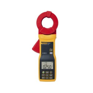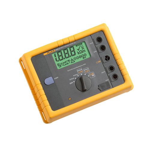
Fluke 1625-2 GEO Earth Ground Tester
- Versatile Measurement Methods:
- 3-Pole and 4-Pole Fall-of-Potential methods
- Stakeless measurement using two clamps
- Automatic Frequency Control (AFC): Ensures accurate measurements in various environments.
- R Measurement:* Calculates earth ground impedance at 55 Hz for accurate reflection of fault-to-earth ground resistance.
- Adjustable Limits: Allows for faster testing by setting customized pass/fail thresholds.
- Rugged and Durable Design: Built to withstand harsh environments.
- Easy-to-Use Interface: Intuitive interface for quick and efficient operation.
- Data Storage and Download: Stores measurement data and transfers it to a PC for detailed analysis.
- Description
- Additional information
- Specifications
- Models
Description
The Fluke 1625-2 is a versatile earth ground tester designed to provide accurate and reliable measurements in a variety of applications. This innovative tool offers multiple testing methods, including:
Traditional Methods:
- 3-Pole Fall-of-Potential: Measures earth ground resistance using two ground stakes.
- 4-Pole Fall-of-Potential: Provides more accurate measurements, especially in high-resistance environments.
Innovative Stakeless Method:
- Stakeless Testing: Measures earth ground loop resistance using only two clamps, eliminating the need for ground stakes. This method is ideal for testing in areas where driving stakes is difficult or impossible, such as indoor installations or paved surfaces.
Key Features:
- Automatic Frequency Control (AFC): Minimizes the impact of interference on measurements.
- R Measurement:* Calculates earth ground impedance at 55 Hz for accurate reflection of fault-to-earth ground resistance.
- Adjustable Limits: Allows for faster testing by setting customized pass/fail thresholds.
- Rugged and Durable Design: Built to withstand harsh environments.
- Easy-to-Use Interface: Intuitive interface for quick and efficient operation.
Applications:
- Electrical Installations: Testing the grounding systems of buildings, power plants, and industrial facilities.
- Telecommunications: Ensuring the integrity of grounding systems in telecommunications infrastructure.
- Utility Companies: Verifying the effectiveness of grounding systems in power distribution networks.
- The Fluke 1625-2 is a valuable tool for electrical professionals who need to ensure the safety and reliability of electrical systems.
By offering a variety of testing methods and advanced features, this instrument provides accurate and efficient earth ground testing.
Additional information
| Brand | Fluke |
|---|
Specifications: Fluke 1625-2 GEO Earth Ground Tester
| General Specifications | ||||
| Memory | Internal memory storage up to 1500 records accessible via USB port | |||
| Measuring function | Interference voltage and frequency, earthing resistance 3- and 4-pole with/without clip-on current transformer, resistance 2-pole with AC, 2- and 4-pole with DC | |||
| Display | 4 digit (2999 Digit) – 7 segment liquid crystal display, with improved visibility | |||
| Operation | Central rotary switch and function keys | |||
| Temperature Range | ||||
| Operating temperature | -10°C to 50°C (14°F to 122°F) | |||
| Storage temperature | -30°C to 60°C (-22°F to 140°F) | |||
| Temperature coefficient | ±0.1% of reading/°C < 18°C > 28°C | |||
| Type of protection | IP56 for case, IP40 for battery door according to EN60529 | |||
| Max voltage | Warning – socket “clamp” to socket E, ES, S or H | |||
| Urms = 0 V | ||||
| Sockets E, ES, S or H to each other in any combination, max. Urms = 250 V (pertains to misuse) | ||||
| Safety | Protection by double and/or reinforced insulation. Max. 50 V to earth per IEC61010-1. Pollution degree 2 | |||
| Quality standard | Developed, designed and manufactured to comply with DIN ISO 9001 | |||
| External field influence | Complies with DIN 43780 (8/76) | |||
| Auxiliary power | 6 x 1.5 V alkaline (IEC LR6 or type AA) | |||
| Battery life span | With IEC LR6/type AA: typ. 3,000 measurements (RE+RH ≤ 1 kΩ) | |||
| With IEC LR6/type AA: typ. 6,000 measurements (RE + RH > 10 kΩ) | ||||
| Dimensions (W x H x D) | 250 x 133 x 187 mm (9.75 x 5.25 x 7.35 in) | |||
| Weight | ≤ 1.1 kg (2.43 lb) without accessories 7.6 kg (16.8 lb) incl. accessories and batteries in carrying case | |||
| Case material | Polyester | |||
| Measurement of Interference Voltage DC + AC (UST) | ||||
| Measuring limits of error: method | Full wave rectification | |||
| Measuring range | 1 V to 50 V | |||
| Display range | 0.0 V to 50 V | |||
| Resolution | 0.1 V | |||
| Frequency range | DC/AC 45 Hz to 400 Hz sine | |||
| Accuracy | ±(5% of rdg + 5 digit) | |||
| Measuring sequence | Approx. 4 measurements/s | |||
| Internal resistance | Approx. 1.5 MΩ | |||
| Max. overload | Urms = 250 V | |||
| Measurement of Interference Frequency (F) | ||||
| Measuring limits of error: method | Measurement of oscillation period of the interference voltage | |||
| Measuring range | 6.0 Hz to 400 Hz | |||
| Display range | 16.0 Hz to 299.9 Hz to 999 Hz | |||
| Resolution | 0.1 Hz to 1 Hz | |||
| Range | 1 V to 50 V | |||
| Accuracy | ±(1% of rdg + 2 digit) | |||
| Earthing Resistance (RE) | ||||
| Measuring method | Current and voltage measurement with probe as IEC61557-5 | |||
| Open circuit voltage | 20/48 V, AC | |||
| Short circuit current | 250 mA AC | |||
| Measuring frequency | 94, 105, 111, 128 Hz selected manually or automatic. (AFC) 55 Hz in function R1 | |||
| Noise rejection | 120 dB (16 2/3 , 50 , 60, 400 Hz) | |||
| Max. overload | Urms = 250 V | |||
| Electrical Measurement Specifications | ||||
| Intrinsic Error or Influence Quantity | Reference Conditions or Specified Operating Range | Designation Code | Requirements or Test in Accordance with the Relevant Parts of IEC 1557 | Type of Test |
| Intrinsic error | Reference conditions | A | Part 5, 6.1 | R |
| Position | Reference position ±90° | E1 | Part 1, 4.2 | R |
| Supply voltage | At the limits stated by the manufacturer | E2 | Part 1, 4.2, 4.3 | R |
| Temperature | 0°C and 35°C | E3 | Part 1, 4.2 | T |
| Series interference voltage | See 4.2 and 4.3 | E4 | Part 5, 4.2, 4.3 | T |
| Resistance of the probes and auxiliary earth electrodes | 0 to 100 x RA but ≤ 50 kΩ | E5 | Part 5, 4.3 | T |
| System frequency | 99% to 101% of the nominal frequency | E7 | Part 5, 4.3 | T |
| System voltage | 85% to 110% of the nominal voltage | E8 | Part 5, 4.3 | T |
| Operating error | B = ±(|A| + 1,15 √E21 E22 E23 E24 E25 E26 ) | Part 5, 4.3 | R | |
| B[%] = ± B/fiducial value x 100%
A = intrinsic error |
||||
| Measuring range | 0.020 Ω to 300 kΩ | |||
| Display range | 0.001 Ω to 2.999 Ω | |||
| 3.00 Ω to 29.99 Ω | ||||
| 30.0 Ω to 299.9 Ω | ||||
| 0.300 kΩ to 2.999 kΩ | ||||
| 3.00 kΩ to 29.99 kΩ | ||||
| 30.0 kΩ to 299.9 kΩ | ||||
| Resolution | 0.001 Ω | |||
| 0.01 Ω | ||||
| 0.1 Ω | ||||
| 1 Ω | ||||
| 10 Ω | ||||
| 100 Ω | ||||
| Accuracy | ±(2% of rdg + 2 digit) | |||
| Operating error | ±(5% of rdg + 5 digit) | |||
| Measuring time | Typical 8 seconds with a fixed frequency 30 sec. max. with AFC and complete cycle of all measuring frequencies | |||
| Additional error because of probe-and auxiliary earth electrode resistance | RH(RS + 2000 Ω)/RE x 1.25 x 10⁻⁶% + 5 digits | |||
| Measuring error of RH and RS | Typ. 10% of RE + RS + RH | |||
| Max. probe resistance | ≤ 1 MΩ | |||
| Max. auxiliary earth electrode resistance | ≤ 1 MΩ | |||
| Automatic check if error is kept within the limits required by IEC61557-5. If after a measurement of probe-, auxiliary earth electrode- and earthing resistance, a measurement error of higher than 30% is assumed because of the influencing conditions, the display shows a warning symbol and a notice that RS or RH are too high. |
||||
| Automatic Switchover of Measuring Resolution in Dependence to Auxiliary Earth Electrode Resistance RH | ||||
| RH with Umeas = 48 V | < 300 Ω | |||
| < 6 Ω | ||||
| < 60 Ω | ||||
| < 600 Ω | ||||
| RH with Umeas = 20 V | < 250 Ω | |||
| < 2.5 kΩ | ||||
| < 25 kΩ | ||||
| < 250 kΩ | ||||
| Resolution | 1 mΩ | |||
| 10 mΩ | ||||
| 100 mΩ | ||||
| 1 Ω | ||||
| Selective Measurement of the Earthing Resistance (RE Clamp) | ||||
| Measuring method | Current and voltage measurement with probe as per EN61557-5 and current measurement in the individual branch with additional current transformer (patent applied for). | |||
| Open circuit voltage | 20/48 V AC | |||
| Short circuit current | 250 mA AC | |||
| Measuring frequency | 94, 105, 111, 128 Hz selected manually or automatically (AFC), 55 Hz (R1) | |||
| Noise rejection | 120 dB (162/3, 50, 60, 400 Hz) | |||
| Max. overload | Max. Urms = 250 V (measurement will not be started) | |||
| Measuring range | 0.020 Ω to 300 kΩ | |||
| Display range | 0.001 Ω to 2.999 Ω | |||
| 3.00 Ω to 29.99 Ω | ||||
| 30.0 Ω to 299.9 Ω | ||||
| 0.300 kΩ to 2.999 kΩ | ||||
| 3.00 kΩ to 29.99 kΩ | ||||
| Resolution | 0.001 Ω | |||
| 0.01 Ω | ||||
| 0.1 Ω | ||||
| 1 Ω | ||||
| 10 Ω | ||||
| Accuracy | ±(7% of rdg + 2 digit) | |||
| Operating error | ±(10% of rdg + 5 digit) | |||
| Additional error because of probe- and auxiliary earth typ. electrode resistance | RH(RS + 2000 Ω)/RETOTAL x 1.25 x 10⁻⁶% + 5 digits | |||
| Measuring error of RH and RS | Typ. of 10% of RETOTAL + RS + RH | |||
| Measuring time | Typ. 8 sec. with a fixed frequency 30 sec. max. with AFC and complete cycle of all measuring frequencies. | |||
| Minimal current in single branch to be measured | 0.5 mA | With transformer (1000:1) | ||
| 0.1 mA | With transformer (200:1) | |||
| Max. interference current through transformer | 3 A | With transformer (1000:1) | ||
| 1. With recommended current clamps/transformers. | ||||
| Resistance Measurement (R~) | ||||
| Measuring method | Current and voltage measurement | |||
| Measuring voltage | 20 V AC, square pulse | |||
| Short circuit current | > 250 mA AC | |||
| Measuring frequency | 94, 105, 111, 128 Hz selected manually or automatically (AFC) | |||
| Measuring range | 0.020 Ω to 300 kΩ | |||
| Display range | 0.001 Ω to 2.999 Ω | |||
| 3.00 Ω to 29.99 Ω | ||||
| 30.0 Ω to 299.9 Ω | ||||
| 300 Ω to 2999 Ω | ||||
| 3.00 kΩ to 29.99 kΩ | ||||
| 30.0 kΩ to 299.9 kΩ | ||||
| Resolution | 0.001 Ω | |||
| 0.01 Ω | ||||
| 0.1 Ω | ||||
| 1 Ω | ||||
| 10 Ω | ||||
| 100 Ω | ||||
| Accuracy | ±(2% of rdg + 2 digit) | |||
| Operating error | ±(5% of rdg + 5 digit) | |||
| Measuring time | Typical 6 seconds | |||
| Max. interference voltage | 24 V, with higher voltages measurement will not be started | |||
| Max overload | Urms max. = 250 V | |||
| Resistance Measurement (R DC) | ||||
| Measuring method | Current- voltage measurement as per IEC61557-4 possible | |||
| Measuring voltage | 20 V DC | |||
| Short circuit current | 250 mA DC | |||
| Formation of measured value | With 4-pole measurement wires on H, S, ES can be extended without additional error. Resistances > 1 Ω in wire E can cause additional error of 5m Ω/Ω. |
|||
| Measuring range | 0.020 Ω to 300 kΩ | |||
| Display range | 0.001 Ω to 2.999 Ω | |||
| 3.00 Ω to 29.99 Ω | ||||
| 30.0 Ω to 299.9 Ω | ||||
| 300 Ω to 2999 Ω | ||||
| 3.0 kΩ to 29.99 kΩ | ||||
| 30.0 kΩ to 299.9 kΩ | ||||
| Resolution | 0.001 Ω | |||
| 0.01 Ω | ||||
| 0.1 Ω | ||||
| 1 Ω | ||||
| 10 Ω | ||||
| 100 Ω | ||||
| Accuracy | ±(2% of rdg + 2 digit) | |||
| Operating error | ±(5% of rdg + 5 digit) | |||
| Measuring sequence | Approx. 2 measurements/s | |||
| Measuring time | Typical 4 second including reversal of polarity (2-pole or 4-pole) | |||
| Maximum interference voltage | ≤ 3 V AC or DC, with higher voltages measurement will not be started | |||
| Maximum inductivity | 2 Henry | |||
| Maximum overload | Urms = 250 V | |||
| Compensation of Lead Resistance (RK) | ||||
| Compensation of lead resistance (RK) can be switched on in functions RE 3-pole, RE 4-pole (clamp), R AC, and R DC 2-pole | ||||
| Formation of measured value | Rdisplay = Rmeasured – Rcompensated2 | |||
| 2. Value of setpoint entry RK = 0.000 Ω, variable from 0.000 to 29.99 Ω by means of measuring adjustment. | ||||
| Stakeless Ground Loop Measurement (Two Clamp Stakeless) | ||||
| Switch position | RA 4-pole (two clamp Stakeless) | |||
| Resolution | 0.001 Ω to 0.1 Ω | |||
| Measuring range | 0.02 Ω to 199.9 Ω | |||
| Accuracy | ±(7% rdg + 3 digit) | |||
| Operating error | ±(10% rdg + 5 digit) | |||
| Measuring voltage | Vm = 48 V AC (primary) | |||
| Measuring frequency | 128 Hz | |||
| Noise current (IEXT) | Max. IEXT = 10 A (AC) (RA < 20 Ω) | |||
| Max. IEXT = 2 A (AC) (RA > 20 Ω) | ||||
| Measuring principle: Stakeless measurement of resistance in closed loops using two current transformers. Automatic range selection. The information regarding stakeless ground loop measurements is only valid when used in conjunction with the recommended current clamps at the minimum distance specified. |
||||
Models: Fluke 1625-2 GEO Earth Ground Tester
Includes:
- GEO Earth Ground Tester
- User’s Manual
- Batteries
- Quick Reference Guide
- USB Cable